 |
OpenSWMM Engine
6.0.0-alpha.4
Data-oriented, plugin-extensible SWMM Engine (6.0.0-alpha.4)
|
|
OpenSWMM Engine
6.0.0-alpha.4
Data-oriented, plugin-extensible SWMM Engine (6.0.0-alpha.4)
|
Chapter 6 drove a mesh with water spilled from the network. The other way to drive one is to rain on it directly, and then the mesh is doing hydrology: catching rainfall, losing part of it into the ground, running the rest downhill, and handing what reaches a drain to the network.
That raises three questions a subcatchment never has to answer. Which gage does a cell listen to, when there are several? What does each cell do with the water that soaks in? And where does that water go — out of the model, into the old per-subcatchment aquifer, or into the aquifer on the mesh itself?
Deck: docs/figures/decks/mesh_hydrology/mesh_hydrology.inp
A 20 × 20 m patch of ground, meshed as eight triangles over nine vertices, falling gently toward a drain at the centre that is coupled to a junction. Two rain gages stand at opposite sides reading 20 and 5 mm/hr, so the interpolation has something to interpolate. Three soil tags — lawn, paved and woods — give the cells three infiltration methods. One hour of rain, two hours of recession.
The deck is written for this chapter rather than copied: it is the smallest model that exercises all three questions at once.
Two gages, each with coordinates, because an un-located gage cannot be interpolated:
The mesh's own options select the rainfall mode and the infiltration destination:
Infiltration resolves per cell, by tag, with a mesh-wide fallback:
and the aquifer beneath is configured the same way:
One warning worth reading. The first version of this deck gave the coupling point an exchange area of 1 m² and the engine said:
2D-coupled node 'J1' has exchange AREA 1.000 m² — 14x the largest connected conduit area (0.0707 m²). The orifice can inject far more than the pipe can convey; expect the node to fill and spill back each window.
The deck now uses 0.07 m², the pipe's own area. An exchange area is the size of the hole between the surface and the network, not the size of the puddle above it.
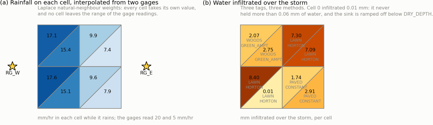
Figure 7-1 Interpolated rainfall and infiltrated depth on each cell of a meshed patch of ground
Every cell takes its own rainfall. Panel (a): the cells nearest the 20 mm/hr gage receive 17.6 mm/hr, those nearest the 5 mm/hr gage 7.4, and the rest lie between. The Laplace natural-neighbour weights reproduce a linear field exactly and never leave the range of the gage readings, so no cell can receive more than 20 or less than 5. With one gage, or with RAINFALL_MODE SYSTEM, every cell would receive the same depth and the whole distinction would vanish.
Each cell infiltrates by its own method. Panel (b): the lawn cells run Horton, the paved cells a constant rate, the wooded cells Green-Ampt, and the amounts differ by a factor of eight across the patch. Part of that is the method and part is the water available — the cell that infiltrated 0.01 mm never held more than 0.06 mm of water, and both sinks ramp off below DRY_DEPTH. Infiltration is limited by supply as much as by soil.
| Term | Volume (m³) |
|---|---|
| Rainfall inflow | 5.001 |
| Infiltration loss | 1.614 |
| 2D → 1D drain outflow | 3.235 |
| Final stored volume | 0.152 |
| Continuity error | 0.000 % |
Table 7-1 The 2D surface water balance for the storm
Just under a third of the rain went into the ground and just under two thirds reached the drain. That split is the answer the mesh exists to give: a subcatchment would have produced one runoff hydrograph with one infiltration loss, and would not have said which part of the ground did what.
The destination key is checked at open, not ignored. Setting INFIL_DESTINATION SUBCATCH_AQUIFER on this deck stops the run:
2D initialization failed: [2D_OPTIONS] INFIL_DESTINATION SUBCATCH_AQUIFER needs subcatchments with aquifers to receive the recharge; this model has none.
which is the right behaviour — the alternative is a model that silently loses its recharge. LOST and AQUIFER_2D both run here, and the surface ledger is identical under both: the surface has finished with the water either way, and the difference is what happens to it next.
The mesh aquifer's own state — the water table, the unsaturated store, the exchange with the node — is configured in this deck and is not plotted here. Its theory, its state variables, its closures and its continuity ledger are in Hydrology 9, and its non-Gardner soil laws carry Experimental. A worked example of the aquifer itself belongs with those, and is not in this round.
 1.13.2