 |
OpenSWMM Engine
6.0.0-alpha.4
Data-oriented, plugin-extensible SWMM Engine (6.0.0-alpha.4)
|
|
OpenSWMM Engine
6.0.0-alpha.4
Data-oriented, plugin-extensible SWMM Engine (6.0.0-alpha.4)
|
A one-dimensional model reports water leaving a node as flooding, and then loses it. For a capacity assessment that is enough. For a flood map, an evacuation route or a depth at a doorway, it is not: the question is where the water goes, how deep it gets, and when it comes back.
Adding a mesh answers that, and adds three things to get right — the mesh, the boundaries, and the coupling between the two solvers. This chapter builds all three on the engine's own complete example.
Deck: docs/figures/decks/coupled_1d2d/2d_complete_example.inp
A deliberately small model: a 1D network of junctions, a storage unit and an outfall, beside a mesh of eight triangles over nine vertices. It is small so that every feature is visible at once — five boundary-condition types, both kinds of coupling point, per-edge conveyance factors — rather than realistic.
The 2D results go to an HDF5 file named by the deck, and both figures on this page are read from it.
The mesh itself is [2D_VERTICES] and [2D_TRIANGLES]; the solver is configured in [2D_OPTIONS]:
The momentum closure is the one key this chapter varies:
Coupling is declared in two ways, and they mean different things.
A vertex map attaches a node to a point of the mesh — a drain inlet in the middle of a street, where the surrounding cells' surfaces are averaged to give the 2D head. A triangle map attaches a node to whole cells, named directly or by tag — a vault or a pond that occupies them. Both use the same orifice law on the head difference, with the discharge coefficient and exchange area the row gives.
Boundaries are per edge, and unlisted boundary edges default to a wall:
Edge e of a triangle is the edge opposite vertex e, which is the one convention to keep in mind when reading or writing these rows.
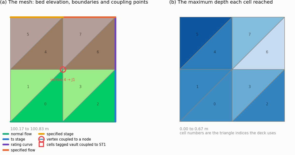
Figure 6-1 The example mesh: bed elevation, the five boundary-condition types and both kinds of coupling point
Panel (a) is the deck drawn from its own results file: the bed rises about 0.7 m from the south-west corner, the coloured perimeter segments are the five boundary types, and the circled vertex is the drain inlet mapped to node J1. Panel (b) is the maximum depth each cell reached.
The run's 2D continuity block is the first thing to read after a coupled run:
| Term | Volume (m³) |
|---|---|
| Rainfall inflow | 0.334 |
| 1D → 2D spill inflow | 2 746.7 |
| Boundary inflow | 4 735.4 |
| 2D → 1D drain outflow | 4 630.3 |
| Boundary outflow | 2 739.8 |
| Final stored volume | 112.3 |
| Continuity error | −0.000 % |
Table 6-1 The 2D Surface Routing Continuity block for this run
Both coupling directions are active: the network spills 2 747 m³ onto the surface and drains 4 630 m³ back off it. A coupled model whose spill and drain rows are both zero is not coupled, whatever its maps say — that is the first check.
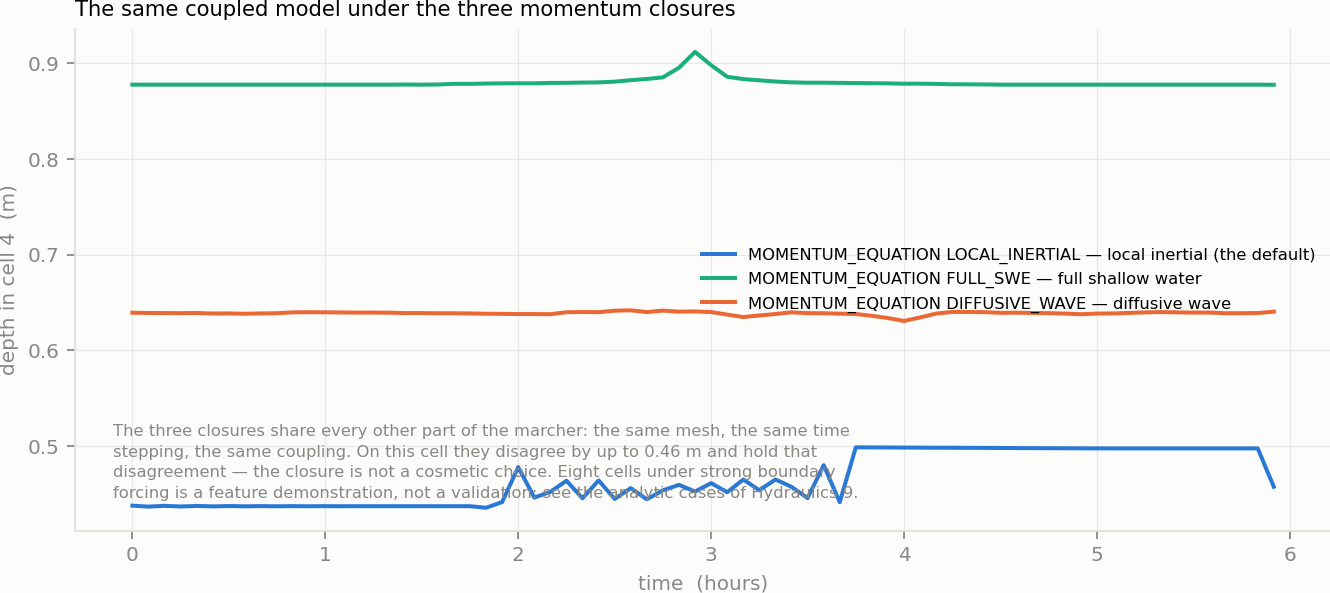
Figure 6-2 One cell's depth history under the three momentum closures
MOMENTUM_EQUATION | Peak depth in cell 4 |
|---|---|
LOCAL_INERTIAL | 0.499 m |
FULL_SWE | 0.912 m |
DIFFUSIVE_WAVE | 0.642 m |
Table 6-2 What each closure gives on this mesh
The three closures share everything else — the same mesh, the same time stepping, the same coupling, the same boundaries — and they disagree here by nearly half a metre, holding that disagreement through the run. The closure is not a cosmetic choice.
What this comparison is not. Eight cells under strong boundary forcing is a feature demonstration, and a spread this large on it says more about the mesh than about the closures. The place to judge them is against analytic solutions — the SWASHES cases in Hydraulics 9, §9.10 — and the guidance from those is the guidance in Chapter 1: local inertial for shallow friction-dominated spreading, full shallow water where the flow is transcritical or shocked, diffusive wave for very flat and slow water. What this figure establishes is that the choice must be made deliberately.
[2D_*] entries — the grammar of every section named here  1.13.2