 |
OpenSWMM Engine
6.0.0-alpha.4
Data-oriented, plugin-extensible SWMM Engine (6.0.0-alpha.4)
|
|
OpenSWMM Engine
6.0.0-alpha.4
Data-oriented, plugin-extensible SWMM Engine (6.0.0-alpha.4)
|
A pipe that is running part full begins to fill. A bore travels down it, the pipe pressurises behind the front, and whatever is at the downstream end — a manhole, a shaft, a surge tank — takes the water and oscillates.
A modeller has to decide how much of that to represent. The dynamic wave router carries one flow per conduit, so the bore is not a front it can place: the conduit fills as a whole. The finite-volume router discretises the conduit and the front is a cell boundary that moves. The question this chapter answers is what the difference is worth, measured against a laboratory pipe where the answer is known.
Deck: docs/figures/decks/rapid_fill/rapid_fill.inp
The rapid-filling experiment of Vasconcelos, Wright and Roe (2006): an acrylic pipe 14.33 m long and 94 mm in diameter, horizontal, initially at rest and 78 % full. A fill box feeds the upstream end and a 0.19 m surge tank closes the downstream one. At t = 0 an inflow of 3.1 L/s is admitted, and pressure at x = 9.9 m, velocity at the same station and the surge-tank level were all measured. The deck carries the paper's own numerics: 400 cells, Courant 0.95, Manning n = 0.012, acoustic celerity 25 m/s.
The two gauge stations are virtual junctions — sealed splices with no storage, transparent to the solution — so the deck also exercises the virtual-junction composition. docs/figures/decks/rapid_fill/provenance.md records where the deck and the three digitised measurement series came from.
The deck as committed is the finite-volume router with its static slot:
The comparison runs change nothing else. The dynamic wave variants are
FV_CELL_LENGTH is the target cell length and FV_MIN_CELLS the floor; 0.036 m over 14.33 m is the paper's 400 cells. FV_SLOT_CELERITY is the pressurised wave speed the slot is sized for — the accuracy-cost trade of Hydraulics 8, §8.4.1, since the explicit step is bounded by \(\Delta x / (|v| + c)\).
Two warnings are expected and correct: INERTIAL_DAMPING and NORMAL_FLOW_LIMITED are dynamic wave keys, and the engine says so rather than ignoring them silently when the deck runs under FV.
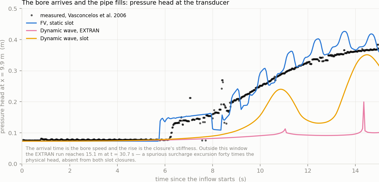
Figure 2-1 Pressure head at x = 9.9 m in the rapid-filling experiment, measured and under three routing choices
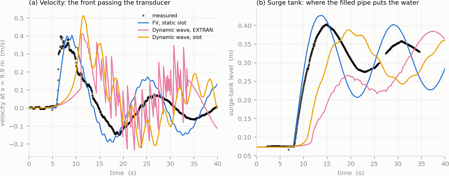
Figure 2-2 Velocity at the transducer and surge-tank level, measured and under the same three choices
| Front arrival at 9.9 m | Surge-tank first peak | Routing continuity error | Run time | |
|---|---|---|---|---|
| Measured | 6.26 s | 0.403 m at 14.8 s | — | — |
FV, static slot | 5.80 s | 0.427 m at 13.8 s | −0.000 % | 17.3 s |
DYNWAVE, slot | 8.75 s | 0.389 m at 19.6 s | 1.147 % | 0.1 s |
DYNWAVE, EXTRAN | 10.90 s | 0.267 m at 19.5 s | 5.655 % | 0.2 s |
Table 2-1 What each formulation reproduces, against the laboratory measurement
Arrival is the first time the head at the transducer passes 0.10 m; the surge-tank peak is the first maximum within 25 s. Every number comes from the runs this page's figures were drawn from.
The front. The finite-volume run puts the bore at the transducer half a second early and reproduces the whole rise; both dynamic wave runs are late by 2.5 s and 4.6 s. That is not a calibration difference. The dynamic wave router has no representation of a front inside a conduit, so the filling of the pipe is spread over the conduit's own storage rather than propagated; the arrival it reports is the arrival of a flow, not of a bore.
The oscillation. The surge tank is the honest test of what happens after filling, because its level integrates everything the pipe did. The finite-volume run peaks 0.024 m high and one second early; the dynamic wave runs peak five seconds late, and the EXTRAN run loses a third of the amplitude.
The velocity trace is where EXTRAN fails visibly. Panel (a) of Figure 2-2 shows it oscillating between ±0.2 m/s from about 13 s onward, at the reporting interval — numerical chatter, not a physical signal. The same run's flow-routing continuity error is 5.655 %, against −0.000 % for the finite-volume run. Outside the plotted window it reaches 15.1 m of head at the transducer, forty times the physical value.
What it costs. Seventeen seconds against a fifth of a second, on a deck of three conduits. The finite-volume router's step is bounded by the Courant condition on the shortest cell, and this deck is 400 cells of 36 mm; the ratio is the price of resolving the front. For a network model the ratio is smaller — cells are metres, not centimetres, and local time stepping (Hydraulics 8, §8.5.6) keeps the quiet parts of the network off the fine clock.
Which one to believe. Here, the finite-volume run, because a laboratory measurement says so. Away from a measurement, the discriminator is continuity: a routing error of 5.655 % on a three-pipe deck with no outfall losses is the solver reporting that it could not close its own books.
 1.13.2